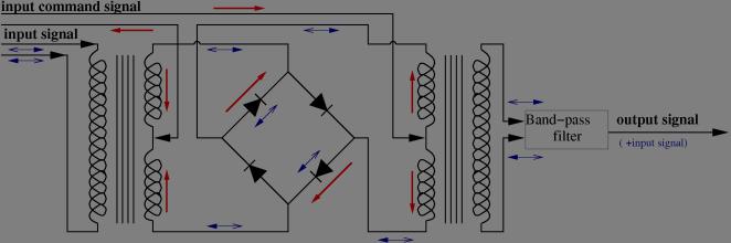
When the command signal is positive (above the diode threshold voltage) the top left & bottom right diodes are conducting while the top right & bottom left ones are isolating. Hence, the output (right hand) transformer recieves directely the input signal from the input (left hand) transformer and the output signal (before the band-pass filter) is the input signals plus a small command signal leak due to the small unbalance between the two inner side transformer coils.
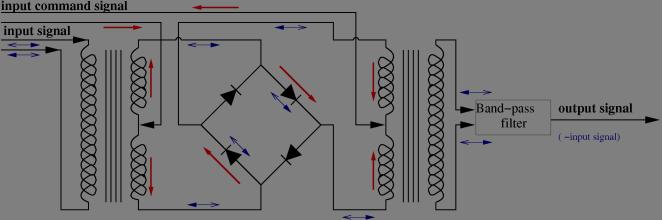
Conversely, when the command signal is negative (below the diode threshold voltage) the top left & bottom right diodes are isolating while the top right & bottom left ones are conducting. Hence, the output (right hand) transformer recieves udside-down the input signal from the input (left hand) transformer and the output signal (before the band-pass filter) is the opposite of the input signals (plus a small command signal leak).
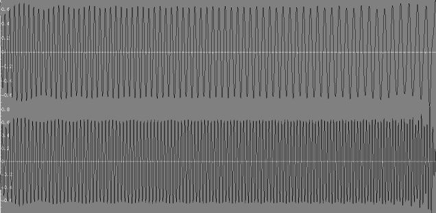
Just to give an idea consider the input signal being a low frequency linear frequency ramp (chirp), and the command signal a constant frequency (the idea is to shift the chirp frequency upwards). The input signal, command and output of the transformer (before the filter) look like this:
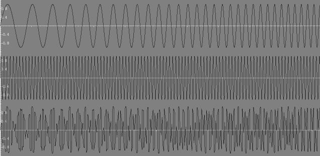
This may seem awkwards, but if we look at the spectra of these signals, we get:
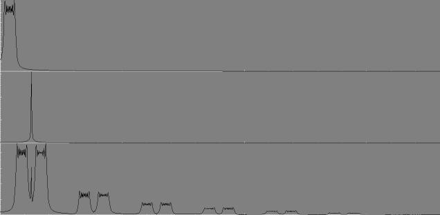
In the output spectra, we recognise the command leak (the sharp peak between the two main lobes), the two frequency shifted input spectra (the two main lobes) and their decaying harmonics (due to the fact that instead of multiplying by the command, the device multiplied by the sign of the command, thus replacing a single sharp peak such as the one in the middle spectrum by a decaying set of peaks (the command frequency and its harmonics, which make the spectrum of a square wave). Indeed, if we filter the lower or the higher we obtain the frequency shifted chirps:
Note that the lower band filtered output is a frequency decreasing chirp (because it is the command minus input signal) unlike both the input and the upper band filtered output (which is the command plus input signal).