Explain the relation between antenna length and angular resolution (by wave analogy) introduce the overall sinc PSF and the concept of diffraction. On the final cross range image, the grey dash is the portion of trajectory (115m long) used as synthetic antenna (thus the synthetic aperture is more like a very narrow slit 10cm high and 115m long (that will be used for Young fringes analogy on cross-track interferometry on chapter 3)
The synthetic antenna is steered by calculation on data playback, and scans the area illuminated by the real antenna (this is the flash-look mode) very rarely used with SAR, but conceptually simple to understand.
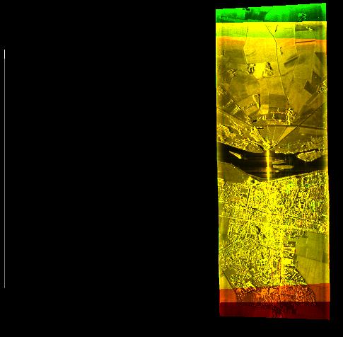
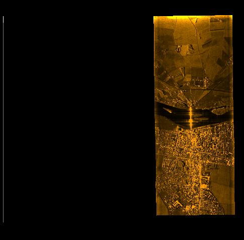
click here to see a 166kB film showing it (if it fails try this link, beware, this is an oddly shaped film 914×276 you might have to disable "aspect ratio" function of your visualiser application, I also suggest to set the "original size" option)Most often, the above described synthetic antenna is used in the strip-map (also called push-broom) mode. Schematically, suppose that we stop the synthetic antenna scanning when it is in the middle of the illuminated area, we would obtain a single line image. But we can the slowly shift the time interval of signal used for synthesis along the whole trajectory (while keeping the steering in the same direction). Visually imagine that the little grey dash on the image slowly drift along the flightpath, this produces an image as this one:
To illustrate its building process, on the image below, the aircraft trajectory is depicted as the grey line on the left, the sliding synthetic antenna of the last computed row of the image (the top one, as the aircraft flies from the bottum up, looking on the right hand side) is the small (100m long indeed) white segment.
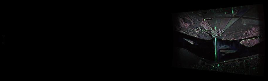
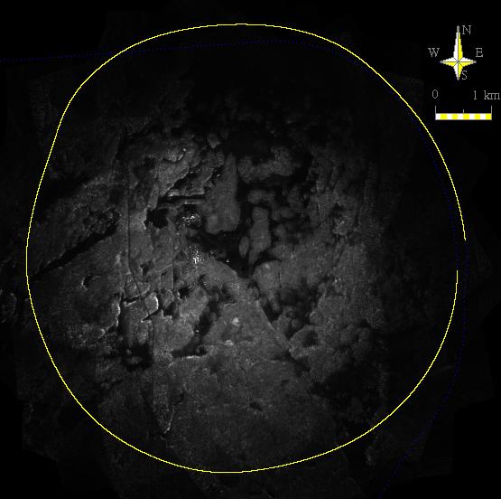
The flash-look mode is however used in case the sensor acquisition trajectory is far from linear, such as in the case illustrated below of circular acquisition trajectory around the imaged area. Another case is that of the spot-light mode, in which the real (small) antenna is steered to a fixed point on the ground thus increasing illumination time (hence resolution and/or number of looks) to the cost of an imaged area that is strongly reduced along-track.
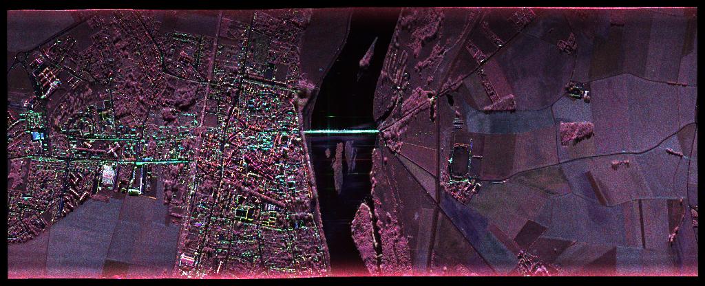
Since the synthetic antenna can be steered to any direction, one can compute stripmap views for several directions relatively to the flight-path. Provided the antenna pattern is wide enough (we shall detail that below) we can compute simultaneously several image of the same area and superimpose them. This technique called "multilooking" is employed to reduce the visual impact of the above mentioned speckle (the grainy aspect of uniform surfaces seen by an imaging radar).